/ Wednesday, 22 February 2017 / No comments / solidworks
Tutorial # 4 : SolidWorks Advance tools Revolve base Revolve cut Mirror Reference geometry and sectional views
In this tutorial we will see some other advance tools of SolidWorks. There are several files available in the download section at the end so you can practice it and modify these files.we will see some concepts about reference geometry,sectional views,Mirror and Revolve base and Cut tools.
Task 1: Revolve Base
Start with a new part, choose the front plane.
Draw the following shape:
Remember, the line going vertical from the origin is a centerline! We will use that as a reference.
Exit Sketch. Click on Revolve Base.
When it asks you to select a plane or previous sketch, select the sketch you just drew. For the Axis of Rotation, select the centerline. You should see something like this.
Note: By default the sketch is rotated 360 degrees, however if your requirement is less you can always modify the amount needed by changing the rotational value. Click OK.
Now, using the view manager, select hidden lines to be visible. Also, select top view. We need both of these to help us complete this part.
Starting from the center, draw an arc of 90 degrees, with a radius of 40mm. Offset the arc by 30mm outwards. Join both arcs with lines to form a segment:
The center line visible is made by creating a line of any length (as long as it isn’t touching anything else – like midpoints, or end points) at an angle of 135 degrees. You can set the angle and dimension of any object by clicking on it. When you click on it, the left hand bar shows the line’s properties. Scroll until you can see the angle value. If the angle value is locked it means your line has fixed relations with other sketch entities.
Click on mirror. Choose the sketch in entities to mirror. You have to choose each individual line separately. Click on Mirror about and choose the centerline. Click Ok when done.
Click on Cut Extrude and click on either segment.
Set depth of cut to 20mm.
NOTE: Mirror, Circular Pattern, and Linear Pattern. These functions are available to you in both sketch mode and feature mode. When to use it depends on the part.
Now, we need to create a groove into the bigger disk of the pulley we’re making.
Select Revolve1 (Look in your feature manager) Right click and select edit sketch. Change view to aid you accordingly.
In edit sketch mode, you can trim or extend entities to suit your need. This is useful for making parts that don’t initially fit together. You will notice that you can change the dimensions of the sketch and the yellow preview of your finished model is visible. The preview stays visible until you modify the sketch to a point where it needs to be rebuilt.
Rebuild (usually represented by an icon that looks like a traffic light) is a function of SolidWorks where the program systematically attempts to automatically make all the steps in the feature manager once you edit something. An error occurs if one of your features is impossible to make. For example, if we move the cut extrude we just made outside the part surface, it would generate an error (since there’s nothing to cut a hole into)
Delete the bottom most 20mm line and replace it with the following sketch. Click Exit Sketch. Click Rebuild.
Task 2: Surface Geometry and Sectional Views
In this tutorial we will make a Piston Head.
Start with a cylinder:
 We need to drill a hole through the cylinder in order to make space for the axle which will connect the piston to the crankshaft. However, if you try to use cut extrude on the curved surface it won’t let you. SolidWorks needs plane surfaces to create features. So we will create a virtual plane for us to work on.
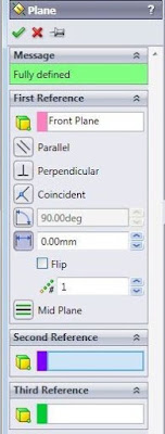
Click on Reference Geometry, then Plane. It is going to ask you for some references to create a plane.
Since this is just a tutorial and therefore easy, just select any one of the two planes (out of top, front and right) which lie on the curved surface. In this example, Top shows a flat circle, whereas right and front show the curved surface)
This will push the plane out of the object.
Now that you have a virtual plane to work on, select that plane, and click on cut extrude. You’ll be asked to make a sketch.
Draw a circle in the center. Roughly 40mm dia would be enough. Exit.
Select through all, and click OK. You’ll see that it bore a hole through the cylinder.
Finally Shell it (use the bottom circular face only) with a wall thickness of 10mm.
With this, we have finished making parts.In next tutorials we will start making assemblies from parts.All these files are available for download in SolidWorks file format.Some additional tasks are also included for your practice.
Press Follow for getting updates about new tutorials.
Press Follow for getting updates about new tutorials.
Related Posts
Subscribe to:
Post Comments (Atom)


No comments:
Post a Comment