
/ Saturday, 25 February 2017 / No comments / Arduino , Mechatronics
Control DC Motor using Relay and Arduino
Control DC Motor Speed using Relay and Arduino

In this quick tutorial you learn how to control speed of dc motor using relay and arduino. Here we learn step by step all process of relays, circuits control for dc motors.
Dc motors is a basic need of electronics. It is used in robotics, projects and industries. Here we learn how to control its speed
Relay and Arduino
A relay is called an electromagnetic switch.Which can be operated by a low electric current that can convert into much larger electric current. As an input signals the voltage and current applied to the coil for opens or closed the contacts of electromagnetic switch .The definition of Relay is: Using electromagnetic attraction activate the contact, which can be produced by giving an electric current that exceed the specified value flows to the electromagnet.
When the current passes through the coil it generates electric field . Which makes close and opens (makes or break) the contact with fixed contact.
Arduino we use for switching the relay how-to-control-relay-switching -with-arduino. Here we learn the concepts of dc motor control using relay with arduino.
Relay control with Arduino
Here we are controlling relay with arduino with simple program and switching the arduino code for controlling speed of dc motor. Here we learn the following main features.- Why use Relay with Arduino.
- How check relay when de-energized.
- How check relay when energized.
- Arduino dc motor control relay circuit.
- Reason of using transistor with arduino and relay.
- Reason of using diode with relay.
- Coding for speed controlling dc motor Arduino for relay.
Why use Relay with Arduino
Normally Microcontrollers (Arduino) drains small amount of current. In some devices we need more current or voltages to run for this purpose we used Relays with Arduino. Here we are using 12 volt and 10 ampere relay. Here we are going to done with blink led control by arduino and relay.How check relay ( Normally open and Normally closed )

There are two terminals working you need to check first.
1) Normally closed terminal (NC).
2) Normally open terminal(NO).
Normally closed terminal (NC) when coil is de-energized
When the relay is not energized . Check resistance across NC and COM terminal with multimeter. The resistance across them is '0 ' (zero). If the resistance across them is zero then the NC terminal is fine.
Here i am providing detail step by step to test NC terminal.
1) First Put the multimeter settings at ohm meter.
2) Put one of the multimeter probe on NC and the other probe on COM.
3) Read Resistance across them.
4) If the resistance is zero '0'. Your NC terminal working fine.
Normally open terminal (NO) when coil is de-energized
When the relay is not energized . Check resistance across NO and COM terminal with multimeter. The resistance across them is several MΩ ( mega ohms ). If the resistance across them is in MΩ then the NO terminal is fine.
Here i am providing detail step by step to test NO terminal.
1) First Put the multimeter settings at ohm meter.
2) Put one of the multimeter probe on NO and the other probe on COM.
3) Read Resistance across them.
4) If the resistance is in MΩ. Your NO terminal working fine.
Relay is energize
Energize the relay by using any external appropriate voltage source for rating of relay coil. Make sure your voltage source is connected with right polarity. When it is connected and relay is energized listen the voice of click.
Normally closed terminal (NC) when coil is energized
when relay is energized. When connect the probes of multimeter with NC and COM. You find opposite condition of de-energized. Here you got infinite resistance or resistance in MΩ. In energized case if resistance is in MΩ then your NC (normally closed ) terminal of relay is working fine.
Normally open terminal (NO) when coil is de-energized
when relay is energized. When connect the probes of multimeter with NO and COM. You find opposite condition of de-energized. Here you got zero resistance across this terminal. In energized case if resistance you got is zero then your NO (normally open ) terminal of relay is working fine.
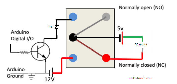
Arduino Relay DC motor Control Circuit
Remember
One of the most important things we should also find is our relay coil resistance. This is for measuring current.
First of all we should find the coil in relay. Mostly it is at pin 2 and 5 as labelled . If not then you have to check resistance at every pin.
Between these two pins you got resistance between 100Ω to 10 KΩ. Here i found 4200 ohms resistance.
Now calculating current
V = I.R
so I = V/R = 12/4200
I = 28 mA.
Arduino can drain 20 mA current and need 28mA to switch relay. So we use npn P2N2222A transistor.
Reason of using transistor with relay
If you supply 5v directly to the coil of 12volt relay using IO pin of arduino maybe the current is not enough to switch the latch since 5v / 400 ohm = 0.0125 A or ~13mA compare to typical 30mA of 12v relay. So you have to use a transistor as a switch so that you can use 5v source of arduino to switch on 12v source to power the relay. Any 12v source would be fine if it is able to provide current larger than 30mA.
If you use 5v relay and use arduino IO pin to drive the relay directly, the coil resistor is around 70 ohm which needs ~71mA to work. This time 71mA excess the absolute 40mA current limit of arduino IO pin. It will likely damage your arduino. So again, you have to use transistor as a switch to amplify the current apply to the relay coil.
Reason of using diode with relay coil
The diode which is used is called flyback diode. The reason is if relay coil is charged it has magnetic field around it and if we turn OFF the relay a back emf comes which could harm our transistor. For pretending the back emf we use flyback diode with relay coil.
Arduino Relay Speed Controlling Code
int motorpin = 6;
void setup()
{
pinMode(motorpin, OUTPUT);
Serial.begin(9600);
while (! Serial);
Serial.println("Speed 0 to 255");
}
void loop()
digitalWrite(motorpin,HIGH);
{
void setup()
{
pinMode(motorpin, OUTPUT);
Serial.begin(9600);
while (! Serial);
Serial.println("Speed 0 to 255");
}
void loop()
digitalWrite(motorpin,HIGH);
{
if (Serial.available())
{
int speed = Serial.parseInt();
if (speed >= 0 && speed <= 255)
{
analogWrite(motorpin, speed);
}
}
}
int speed = Serial.parseInt();
if (speed >= 0 && speed <= 255)
{
analogWrite(motorpin, speed);
}
}
}
You have successfully completed one more Arduino "How to" tutorial.
I hope you liked this, if you have any query let me know in the comments.
There will be more of them, so make sure to click Follow button!
Subscribe to:
Post Comments (Atom)


No comments:
Post a Comment